Basic Flow
This section covers the basic steps to create a flow in the Flow Designer. Before you create a flow, you need to have started the server and created a developer user in the management console -- see Starting the Server for the First Time and Creating an Account for procedures.
See the following sections for overviews and links to more information:
Or, start the tutorial from the Flow Designer:
Accounts
Authenticating to a Domain
When you connect to the server, you are prompted to authenticate your user account against the domain that the account belongs to. If you are connecting to a subdomain, you need to specify the domain name. Otherwise, the user is authenticated against the root domain.
Specify the domain with the full name, the domain name and user name separated by a slash, as in "/Workshop/user1". Specify the root domain with "/" as in "/developer1".
Managing User Accounts
During the installation, you create the system administrator account and a Flow Service user account. You need at least these two separate roles in your system: a system administrator and a flow developer.
Administrators that belong to the root domain can configure account roles on the Tools > Account page of the management console. For guides to the settings, click Help on the Tools > Account page.
| User | Domain member |
Initial Password | Description |
|---|---|---|---|
| asu | / | Set during installation | The full name is "/asu". This is the system administrator. |
| developer1 | / | Check the "create for development" option and enter a password in the Initial Settings wizard. | The full name is "/developer1". |
Caution
-
The system user "/asu" should not be used to log into the Flow Designer.
-
The system user "/asu" should not be deleted.
Accessing Project Files in the Home Folder
A user's projects and other files owned by the user are stored in the user's home folder. By default the home folder is under the server's data folder. The path is [DATA_DIR]/home. For example:
C:/asteriahome5[c,cp]/home/developer1
Projects and Flows
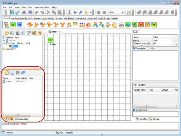
After you connect to the server, your next task is to create a flow in a project. You create flows and projects using the Flow Designer GUI; you can manage the project files in the tree pane.
Projects are defined in XML project files (.xfp), and flows are defined in projects. As you create flows in the Flow Designer, the .xfp files are updated with the flow definitions.
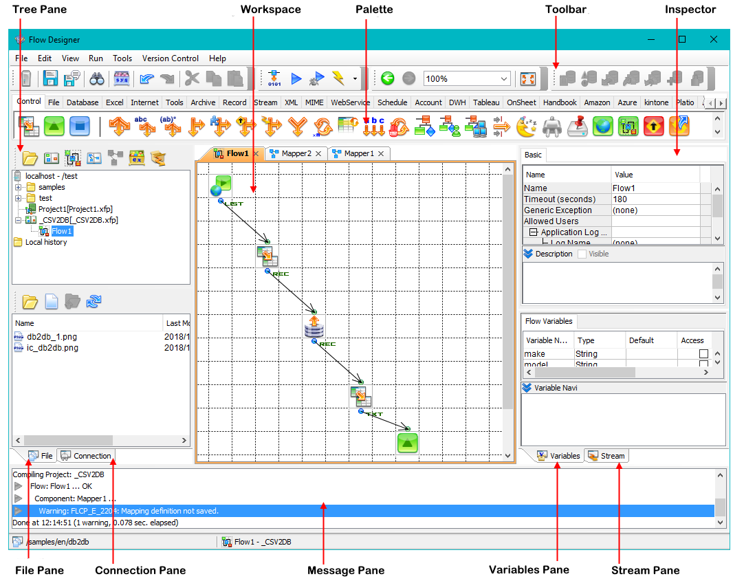
Flow Designer GUI
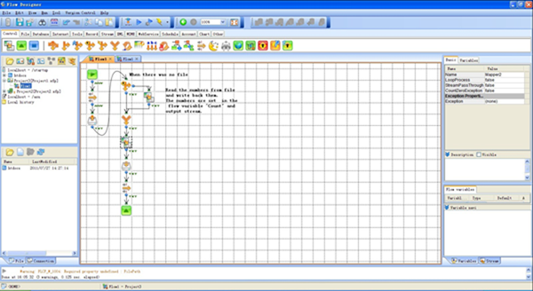
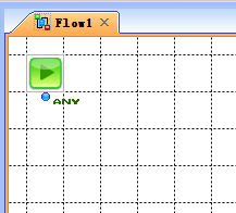
Below is an example flow in the workspace. Components and mappers are linked together to process a stream of data; see the next section, Flow Elements for guides to connecting these and other graphical data integration tools.
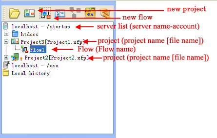
Tree Pane
The tree pane shows the files on the server.
Flow Elements
In the workspace of the Flow Designer, you build flows by connecting the graphical tools below:
Components
A component is a graphical representation of a data-processing operation -- "get a file," "send an email," "insert to a database," etc. To specify the parameters of the processing operation, you can configure the component's properties in the inspector pane.
Drag components from the palette into your flow. In the flow window, you can link components and build the flow using other graphical flow elements. A component processes a stream of data; the arrows that connect the components show the direction of the stream.
See the screenshot below for an example flow.
Flow Designer Workspace
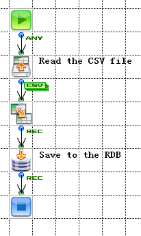
The following example flow reads a CSV file and inserts the data into a relational database. The Mapper component maps the fields of CSV to the destination table's columns.
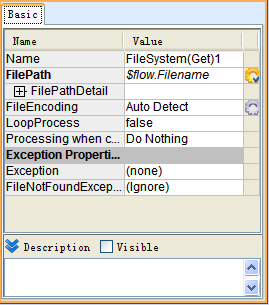
Configuring a Component's Properties
Select a component in the workspace to open its properties in the inspector, shown below.
Inspector
Streams
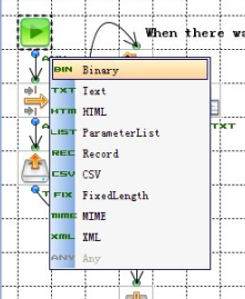
A stream is the data that is transmitted in a flow. You can define the following types of streams to facilitate processing data with the corresponding format: XML, CSV, FixedLength, Record, ParameterList, MIME, HTML, TEXT, and Binary.
To change the stream type, click the label displayed next to the component in the workspace.
Mappers
You can use Mapper components to map an input stream's data to an output stream:
- Adding a mapper: drag the
 component from the Control tab or the Favorites section of any tab in the palette.
 - Creating a mapping: connect an input stream and output stream to the mapper and double-click the mapper to open the mapping window.
Mapper Functions
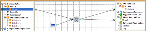
In the mapping window, you link together mapper functions to create graphical data-processing routines, which are similar to the flows you create in the Flow Designer's main workspace. Mapper functions operate on the fields of a stream, manipulating strings, evaluating numeric expressions, evaluating boolean expressions, etc.
Mapping Window
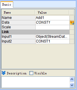
Configuring Mapper Function Properties
Specify the arguments to a mapper function by setting the mapper function's properties: select a mapper function in the mapping window to open its arguments in the inspector.
Inspector
Starting the Server for the First Time
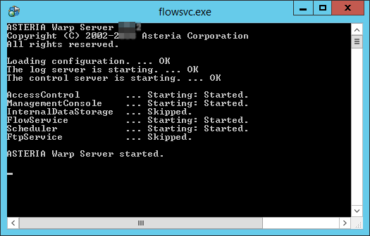
Starting the Flow Service
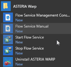
Select Start Flow Service from the Start menu.
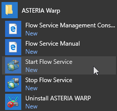
Starting the server
Note
You can also start the server as a Windows service or from the command line on Windows or Linux: see the Flow Service Management chapter in Administration.
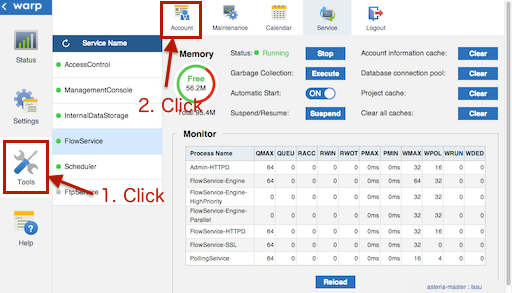
Logging into the FSMC
From the Start menu, select Flow Service Management Console in the Start menu. Or, from the Flow Designer, right-click the server node in the Flow Designer's tree pane. The management console is opened in your default browser.
Below is the default URL:
http://[server]:28080/
Start menu options
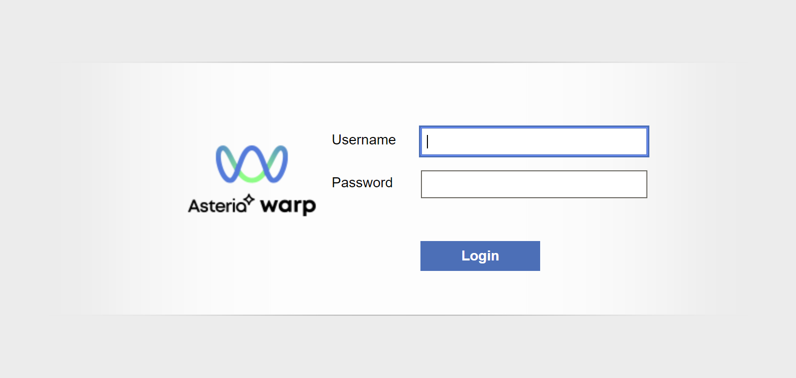
Management Console Login Screen
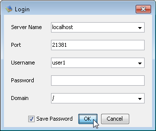
Enter the default password and the admin account's username, for example, "/asu".
Note
By default, users are authenticated against the root domain. If you need to specify a subdomain, use the full-name syntax. For example, "/Workspace/asu".
If you cannot access the login screen, check the following:
- Whether the Flow Service has started or not
- Whether the port number of the management console is being blocked by a proxy
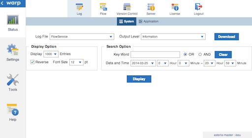
After you log in, the system logs page is displayed.
Creating an Account
Follow the steps below to create a user with the developer role. You'll use this user to work in the Flow Designer.
-
Log into the FSMC and click Tools > Account.
-
Select the root domain, "/", or a subdomain and click Create User. Enter the username and password and select the role.
For more information on the roles, click Help in the management console and then open the Common > Users and Roles section.

Connecting from the Flow Designer
-
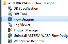
Open the Flow Designer from the Start menu.
-
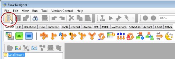
Click the Add Server icon from the toolbar.
-
Select or enter the server, domain, and user.
Caution
The system user "/asu" shouldn't be used to log into the Flow Designer. Use a user with the developer or operator role instead.
After you connect, the server is added to the tree:
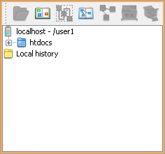
Note
The htdocs folder is created when the user is created.
You can now create data integrations. See the next sections for the basic procedure.
Using the GUI
This document uses the following terms to refer to elements of the Flow Designer's GUI (graphical user interface):
Creating and Testing a Flow
This tutorial covers some typical tasks when creating a flow: processing multiple files and using expressions to set input values dynamically.
After starting the Flow Service, follow the steps below to create a simple flow that combines the text from all files that match the "data*" pattern.
- Creating a Project
- Processing Files in the Home Folder
- Creating a Flow
- Saving the Flow
- Running the Flow
Creating a Project
-
Select the server in the tree pane and click the button to create a new project:
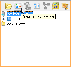
-
Select the New Flow template to create an empty flow.
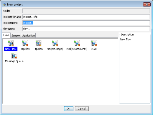
Note
The resulting Flow is empty except for a Start component -- the Start component is required and can't be deleted.
Processing Files in the Home Folder
In the following section, you will create a simple flow that processes all files in the home folder that match a pattern. This section provides some introductory notes about working with files in the home folder.
Default home folder path
The home folder is located under the data folder on the server. Below is the default path to the data folder:
| Windows | C:\asteriahome5[c,cp] |
|---|---|
| UNIX | /[Installation user's home folder]/asteriahome5[c,cp] |
For example: C:\asteriahome\flow\home\user1.
Note
- Creating a flow generates some files that are hidden by default. You can change this in Tools > Settings.
- When you set a component's properties, you can use relative paths from the home folder.
Creating a Flow
Follow the steps below to read and write files with the FileGet and FilePut components. The FileGet component reads all files matching the "data*.txt" pattern. The FilePut component outputs files like data20190330.txt into an "output" folder in the home folder, creating the folder if it does not exist.
- Creating the Sample Data Files
- Adding the FileGet Component
- Adding the FilePut Component
- Adding the End Component
Creating the Sample Data Files
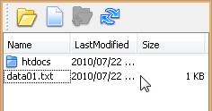
Follow the steps below to create the example files in the file pane of the Flow Designer.
-
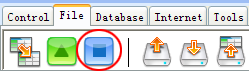
Click the new-file button
 in the toolbar of the file pane.
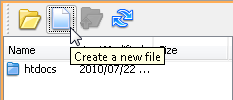
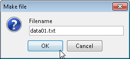
-
Enter "data01.txt" as the filename.
-
Double-click the file in the file pane to open it in your text editor.
-
Enter the file contents as below and save the file:
data010
data011
data012
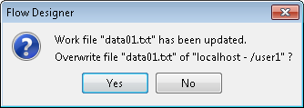
-
A warning that the file has been updated is displayed. Click Yes to overwrite the file.
-
Follow the same steps to create another file named "data02.txt" that includes the following lines:
data020
data021
Adding the FileGet Component
-
Click the File tab in the palette.
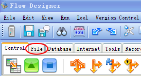
-
Add the FileGet component to the workspace.
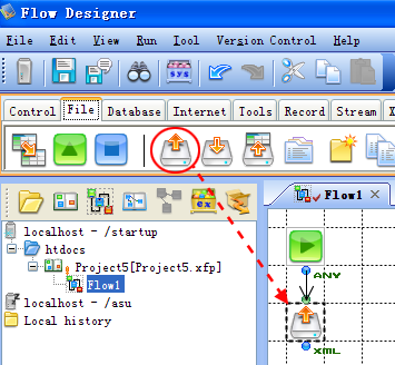
Note
By default, a new component is automatically connected once it is added. Hold Ctrl as you drop in a component to add it without connecting it automatically. You can also configure components to not connect automatically in Tools > Settings.
-
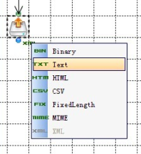
Change the FileGet component's stream type: click the XML label next to the component and select TXT (Text) in the list.
-
Click the component to open the property pane.
-
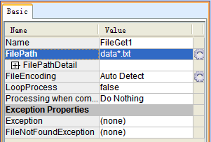
In the FilePath field, enter the file-matching pattern: "data*.txt".
Note
Using wildcards: To read multiple files, you can use wildcards in the File Path property.
Processing multiple files: By default, multiple files are merged into one stream. To process the files one by one, enable looping in the properties for the component.
Adding the FilePut Component
Follow the steps below to use a FilePut component to merge the input files into the output file. You'll generate the filename based on the date; for example, data20190330.txt
-
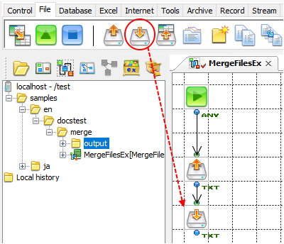
On the File tab, drag the FilePut component from the palette, then drop it into the Flow window.
-
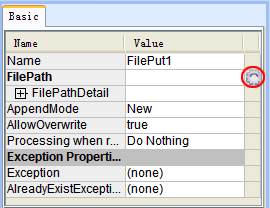
Select the FilePut component in the workspace and click the options button
 next to the File Path property.
-
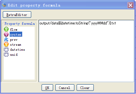
Add the "output/data" part of "output/data20190330.txt".
-
Add the date part: double-click
datetime and double-click "toString("yyyyMMdd")". -
Add the extension, ".txt", to make the entire formula the following: "output/data${datetime.toString("yyyyMMdd")}.txt"
Note
Refer to "Components" > "Component Properties" in the Flow Designer user's guide for more information on using property expressions.
Back to Creating a Flow.
Adding the End Component
Drag and drop the End component onto the palette:
Note
You need to add one of the following components to end the flow.
- EndResponse: The EndResponse component can output its input stream as the flow's result.
- End: The End component doesn't output a result.
This example uses the End component to skip outputting the result.
Back to Creating a Flow.
Saving the Flow
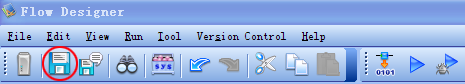
Click the save icon ![]() in the toolbar to save and compile the flow.
in the toolbar to save and compile the flow.
The message pane displays a success message or any errors:
If an error occurred, double-click the error message to go to the position where the error occurred.
Notes
- You can also press Ctrl+S to save a flow.
- You can configure autocompile and autosave settings in Tools > Settings.
Running the Flow
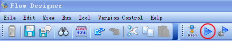
Click the run button ![]() or press F5.
or press F5.
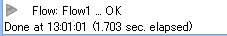
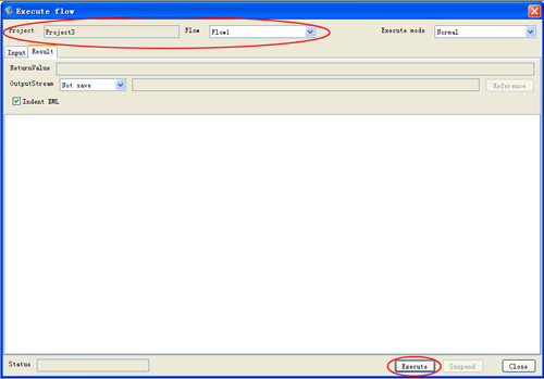
Check that the project and flow are correct. You can find the execution status here after you click Execute.
To check the generated files, click the ![]() refresh button in the toolbar of the file pane. The "output" folder, which contains the generated file, is displayed.
refresh button in the toolbar of the file pane. The "output" folder, which contains the generated file, is displayed.
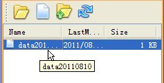
The generated file contains a concatenation of the files:
data010
data011
data012data020
data021